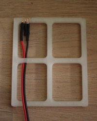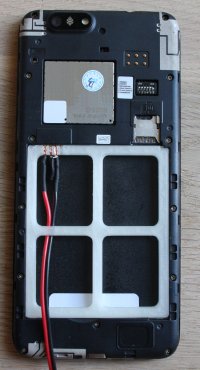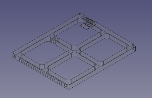
The Pinephone Pro (being a rather new device) doesn’t have a particular good battery life yet.
A such I thought that it might be interesting to hock it up to my lab/bench power supply.
Not so much to power it from it as to allow me to measure the current it draws.
I therefor modeled a adapter in FreeCAD based on measurements taken from the
Pinephone (Pro) battery.
I added some 45° features to make it easier to print that shouldn’t interfere too much with the functionality
of the parts designed to hold the battery in place.

Apart from the 3D printed part you also need:
- Some copper tape (I used some “snail repellent” tape intended for plants).
- A NTC resistor or a regular resistor, I simply used a 2.2kΩ one which seem to read as around 19°C.
- Heat shrink tubing.
The resistor between the NTC and - pin might not be needed, I just didn’t want risk having any issues with the phone freaking out due to the battery reading as having an insane temperature.
The power supply wires are fed through a hole in the adapter giving it a very basic strain relief. I should probably give it a dab of hot glue to secure it in place.
The wires are roughy 70cm long, this is enough to cause problems due to the current draw of the phone.
If the voltage is too low the phone will turn off while booting the OS.
It still works if I turn up the voltage close to the fully charged voltage of the battery.
I haven’t looked into if the problem is inductive or resistive in nature, but a capacitor close to the terminal might solve the problem.
(And as the phone uses DC-DC converters the issues should be addressed before trying to measure power consumption)
WARNING only build this if you know what you are doing!
Reversing the voltage, shorting pins or supplying too high a voltage may instantly DESTROY your phone!

Get you STL file here and the FreeCAD file here